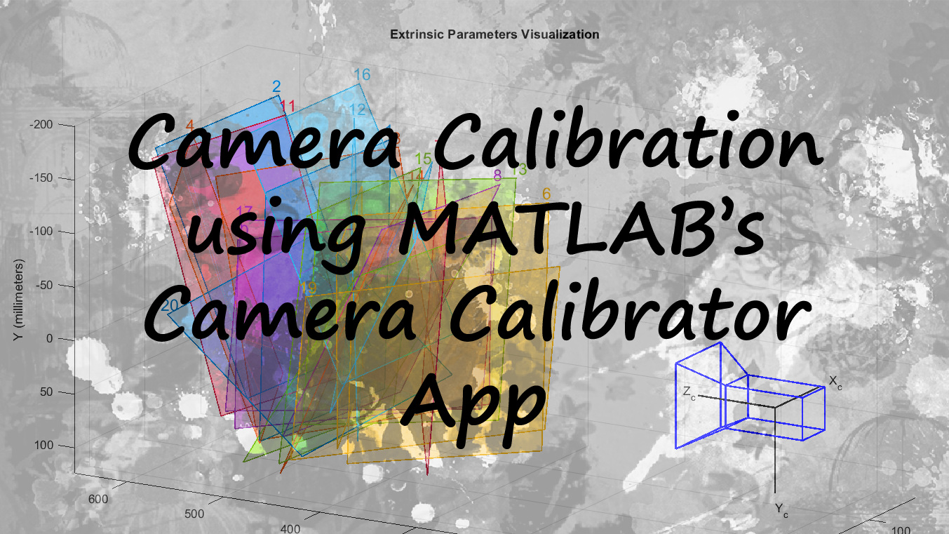
Camera Calibration using MATLAB's Camera Calibrator App
Camera calibration refers to the process of estimating Intrinsic and Extrinsic parameters of a camera using the images captured through the same camera. In this article I have described how it is done using the MATLAB’s Camera Calibrator App which comes under the Image Processing and Computer Vision Toolbox.
I have used my Huawei Y5-2017 Smart Phone’s Back Camera for the process. You may use whatever camera you want. But make sure you can find the technical specifications like sensor width in millimeters or size of a pixel of your camera, to get any useful work done using the results of the Camera Calibration. For the calibration, I designed a Checkerboard pattern myself using Adobe Photoshop, which has 30mm x 30mm squares. You can download it from here. But later I found that out there are checkerboard patterns readily available on the internet😅. Here is the link. Don’t waste your time on designing the checkerboard. Just download one, print and use.
Now all you have to do is take some photos of the checkerboard under good lighting conditions.
Things to keep in mind:
- The checkerboard must be asymmetric: one side should be even, and the other should be odd. Otherwise, the orientation of the board may be detected incorrectly.
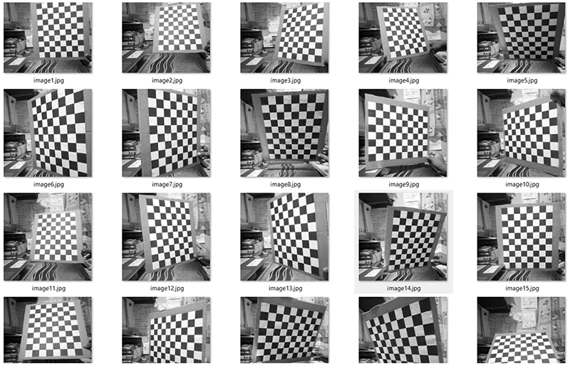
- Take about 20-25 photos of the checkerboard in different orientations and at different distances. The Camera Calibrator App can get the best images out of that and some images may be rejected at the initial steps due to various reasons. Here I have used 20 different images as the following figure illustrates.
- Do not crop or pre-process the images. Just use them as they are. I observed that parameters are slightly affected by doing so. But I am not that sure about it.
- Save all of the photos in one folder as it makes things easy.
Process
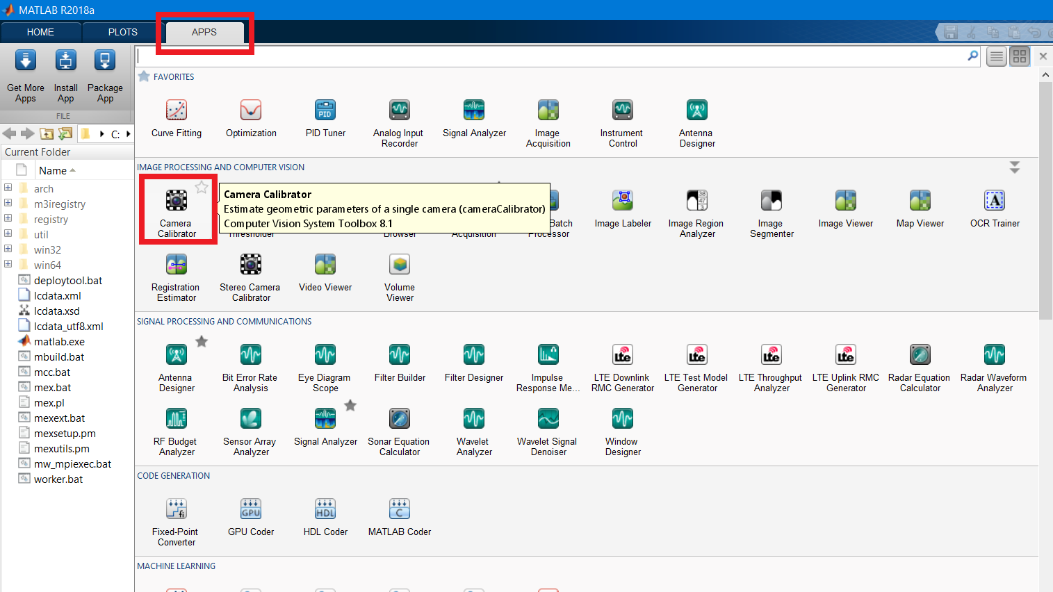
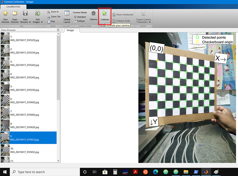
Step 1: Open MATLAB’s Camera Calibrator app comes under the Image Processing and Computer Vision System Toolbox…
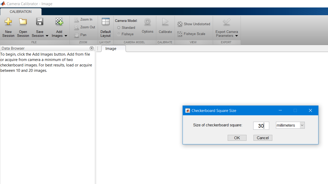
Step 2: Click the Add Images icon and choose the From file option. Now you can select all of your checkerboard images and open them in the Camera Calibrator App…
The program will automatically analyze all the images and detect checkerboards in them and some images may be rejected at this step if they are not suitable for the camera calibration process.

After that, you will have to specify the actual size of a checkerboard square in mm. Here I have used a checkerboard with 30mm x 30mm squares.
Step 3: Click the Calibrate icon and that’s it…
Step 4: This is the final step and you can Export the extracted camera parameters to use in any useful work…
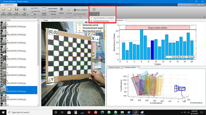
Click Generate MATLAB Script from the Export Camera Parameters drop-down menu and run the script to get the results as follows.
Standard Errors of Estimated Camera Parameters Huawei Y5-2017 Phone's Back Camera
--------------------------------------------------------------------------------

Intrinsics
----------
Focal length (pixels):   [ 2700.1129 +/- 2.8244     2704.0118 +/- 2.6479  ]
Principal point (pixels):[ 1179.3009 +/- 1.8586     1588.6612 +/- 1.4667  ]
Radial distortion:       [    0.0926 +/- 0.0044       -0.2114 +/- 0.0163  ]

Extrinsics
----------
Rotation vectors:
  [    0.1588 +/- 0.0033        0.0631 +/- 0.0032        1.5096 +/- 0.0004  ]
  [   -0.2234 +/- 0.0020        0.4752 +/- 0.0020        1.5148 +/- 0.0005  ]
  [    0.2675 +/- 0.0016        0.7273 +/- 0.0015        1.5628 +/- 0.0005  ]
  [   -0.5501 +/- 0.0016       -0.0713 +/- 0.0017        1.3859 +/- 0.0005  ]
  [    0.5973 +/- 0.0013       -0.3509 +/- 0.0012        1.4462 +/- 0.0005  ]
  [    0.7129 +/- 0.0011        0.5485 +/- 0.0009        1.4374 +/- 0.0003  ]
  [   -0.3825 +/- 0.0010       -0.5195 +/- 0.0010        1.4603 +/- 0.0004  ]
  [    0.5176 +/- 0.0016       -0.3308 +/- 0.0015        1.5007 +/- 0.0004  ]
  [    0.0257 +/- 0.0014       -0.4419 +/- 0.0013       -0.0002 +/- 0.0003  ]
  [    0.0536 +/- 0.0011        0.7438 +/- 0.0011       -0.0341 +/- 0.0004  ]
  [   -0.1150 +/- 0.0022        0.4484 +/- 0.0022        1.5657 +/- 0.0005  ]
  [   -0.4369 +/- 0.0012       -0.3818 +/- 0.0012        1.4392 +/- 0.0004  ]
  [    0.7449 +/- 0.0011        0.5763 +/- 0.0010        1.4086 +/- 0.0004  ]
  [    0.0326 +/- 0.0014       -0.6226 +/- 0.0012        1.5766 +/- 0.0005  ]
  [    0.1588 +/- 0.0025       -0.0428 +/- 0.0025        1.5457 +/- 0.0004  ]
  [   -0.2892 +/- 0.0013        0.4623 +/- 0.0012        1.5130 +/- 0.0004  ]
  [    0.0113 +/- 0.0011        0.7785 +/- 0.0010        0.0270 +/- 0.0004  ]
  [    0.3784 +/- 0.0010       -0.4751 +/- 0.0010        0.0885 +/- 0.0004  ]
  [    0.3874 +/- 0.0008        0.7383 +/- 0.0008       -0.1240 +/- 0.0003  ]
  [   -0.8528 +/- 0.0010        0.1070 +/- 0.0010       -0.0451 +/- 0.0005  ]

Translation vectors (millimeters):
  [  155.9579 +/- 0.3677     -149.0883 +/- 0.2884      504.5399 +/- 0.7126  ]
  [  176.5537 +/- 0.4447     -123.4080 +/- 0.3533      639.8593 +/- 0.6801  ]
  [  180.8317 +/- 0.3672     -134.0703 +/- 0.2782      507.8285 +/- 0.5990  ]
  [   84.0470 +/- 0.4612     -136.3349 +/- 0.3649      669.0573 +/- 0.6390  ]
  [  119.6632 +/- 0.2727      -95.3260 +/- 0.2315      384.8297 +/- 0.5451  ]
  [   82.4593 +/- 0.2097     -132.8647 +/- 0.1609      290.4283 +/- 0.3903  ]
  [  122.0913 +/- 0.2909     -142.2950 +/- 0.2273      429.6691 +/- 0.4322  ]
  [  122.5745 +/- 0.2601     -161.9149 +/- 0.2392      367.3551 +/- 0.5461  ]
  [ -103.7371 +/- 0.2912     -130.3420 +/- 0.2271      402.5284 +/- 0.5192  ]
  [  -66.6782 +/- 0.3670      -95.1525 +/- 0.2852      530.3091 +/- 0.4739  ]
  [  152.3982 +/- 0.4281     -125.6566 +/- 0.3379      615.8554 +/- 0.6698  ]
  [  106.9474 +/- 0.3516     -141.9626 +/- 0.2725      515.0723 +/- 0.5021  ]
  [   76.2934 +/- 0.2354     -131.5001 +/- 0.1804      327.6164 +/- 0.4259  ]
  [  163.2290 +/- 0.3361     -122.9659 +/- 0.2729      484.1596 +/- 0.5847  ]
  [  123.0242 +/- 0.3248     -136.7787 +/- 0.2660      453.6079 +/- 0.6208  ]
  [  121.1290 +/- 0.3582     -172.0656 +/- 0.2864      520.5429 +/- 0.5245  ]
  [  -56.3611 +/- 0.3727      -82.7235 +/- 0.2890      537.3520 +/- 0.4719  ]
  [  -51.0117 +/- 0.2546      -97.1251 +/- 0.2080      355.1822 +/- 0.4898  ]
  [ -125.1265 +/- 0.2795     -110.6333 +/- 0.2286      418.3420 +/- 0.3920  ]
  [ -112.7127 +/- 0.3892      -53.8583 +/- 0.3211      577.6856 +/- 0.5495  ]
Interpretation of the results
Intrinsic Parameters
- Focal length (pixels)
These values simply indicates the focal length of the camera in both x and y directions in pixels.
[ 2700.1129 +/- 2.8244 2704.0118 +/- 2.6479 ]
- Principal point (pixels)
The point where principal axis intersects the image plane is known as the principal point. These values can be used to determine the size of the camera sensor(CCD) in the given units as follows.
[ p_x = 1179.3009 +/- 1.8586 p_y = 1588.6612 +/- 1.4667 ]
- CCD width = 2*p_x
- CCD height = 2*p_y
Extrinsic Parameters
- Rotation vectors (radians)
3-D rotation vectors, specified as a 20-by-3 matrix containing 20 rotation vectors. Each vector describes the 3-D rotation of the camera image plane relative to the corresponding calibration pattern. The vector specifies the 3-D axis about which the camera is rotated, where the magnitude is the rotation angle in radians.
- Translation vectors (millimeters)
Camera translations, specified as a 20-by-3 matrix. This matrix contains translation vectors for 20 images. Each row of the matrix contains a vector that describes the translation of the camera relative to the corresponding pattern, expressed in world units.
There are 6 Principal Movements as, rotations about 3 axes(X,Y,Z) and translations along 3 axes(X,Y,Z). Correct combination(obtain by multiplying required principal matrices like \(Rot(e_i,\theta_m)*Trans(e_j,d_k)\)) of these 6 principal movements can be used to get any of the advanced transformations, from the reference frame to object’s frame. Those basic matrices are as follows where \(e_i\) refers to the elements in standard basis( \(e_1 = [1 ~0~ 0]^\top\), \(e_2 = [0 ~1~ 0]^\top\) and \(e_3 = [0 ~0~ 1]^\top\)) while \(\theta_i\) indicates how many degrees the object has rotated about the \(e_i\) basis vector. Additionally \(d_i\) indicates the displacement along the direction of \(e_i\) basis vector(axis).
| Principal Rotations about axes(X,Y,Z) | Principal Translations along axes(X,Y,Z) |
|---|---|
| \(Rot(e_1,\theta_1) = \begin{bmatrix} 1 & 0 & 0 & 0 \\ 0 & \cos(\theta_1) & -\sin(\theta_1) & 0 \\ 0 & \sin(\theta_1) & \cos(\theta_1) & 0 \\ 0 & 0 & 0 &1 \\ \end{bmatrix}\) | \(Trans(e_1,d_1)= \begin{bmatrix} 1 & 0 &0 & d_1 \\ 0 & 1 & 0 & 0 \\ 0 & 0 & 1 & 0 \\ 0 & 0 &0 & 1 \\ \end{bmatrix}\) |
| \(Rot(e_2,\theta_1) = \begin{bmatrix} \cos(\theta_1) & 0 & \sin(\theta_1) & 0 \\ 0 & 1 & 0 & 0 \\ -\sin(\theta_1) & 0 & \cos(\theta_1) & 0 \\ 0 & 0 & 0 &1 \\ \end{bmatrix}\) | \(Trans(e_2,d_2) = \begin{bmatrix} 1 & 0 &0 & 0 \\ 0 & 1 & 0 & d_2 \\ 0 & 0 & 1 & 0 \\ 0 & 0 & 0 & 1 \\ \end{bmatrix}\) |
| \(Rot(e_3,\theta_1) = \begin{bmatrix} \cos(\theta_1) & -\sin(\theta_1)&0 & 0 \\ \sin(\theta_1) & \cos(\theta_1) &0 & 0 \\ 0&0 &1 & 0 \\ 0 & 0 & 0 &1 \\ \end{bmatrix}\) | \(Trans(e_3,d_3) = \begin{bmatrix} 1 & 0 &0 & 0 \\ 0 & 1 & 0 & 0 \\ 0 & 0 & 1 & d_3 \\ 0 & 0 & 0 & 1 \\ \end{bmatrix}\) |
All the project files, images and stuffs can be found here.